COD Tutorial: How to create polylines based on administrative levels from COD-AB polygons
Introduction
One of the desirable features for COD-AB (and COD-EM) datasets is a line layer with an 'admLevel' attribute field designating the administrative level of each line segment.
| Administrative levels |
|---|
| Administrative boundary Common Operational Datasets (COD-ABs) and Edge-matched Common Operational Datasets (COD-EMs) model the hierarchical administrative structure of a location with nested (often multi-part) polygon layers. The 'highest' administrative level, ADM0, generally corresponds to the entire country or location, for which there is one (normally multi-part) polygon feature. The next administrative level, ADM1, represents the first sub-national administrative level. Terminology for the ADM1 feature types varies widely and could be 'state', 'province', 'oblast', 'governorate' or another term. COD-AB and COD-EM datasets may have as many as five administrative levels (ADM0 to ADM4) depending on relevance an data availability. |
The COD-AB and COD-EM lines layers include a single lines layer, typically composed of the lines forming the lowest administrative level polygons.
The 'admLevel' attribute represents the administrative level or depth of each line feature. Features with 'admLevel' 0 represent international borders (but '99' is specially substituted to represent coastlines); 'admLevel' 1 represents lines between distinct administrative level 1 units, etc.; and integers between 10 and 90 are reserved for special-status boundaries. These files are necessary for the best cartographic symbology. The alternative is to symbolize and sequence all polygon boundaries so that higher level boundaries have dominant symbols, revealing lower level boundaries in between. (Even if these are carefully disguised by symbol size and order, shorelines cannot be symbolized properly.) ITOS makes these line shapefiles when they process COD-AB and COD-EM datasets but if a country is not yet and 'enhanced' COD the coded line file can also be made with the following instructions.
The process may be unnecessary for island or landlocked countries containing only administrative level 0 polygons.
Polygon symbolization example
Colombia ("Colombia - Subnational Administrative Boundaries" COD-AB available on HDX here)
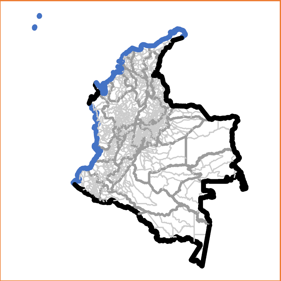
The Colombia COD-AB features administrative levels 0, 1, and 2. To demonstrate the weakness of cartogprahy that does not use the 'admLevel' lines layer, these levels will be symbolized with successively wider and darker lines, with the administrative level 0 (international / shoreline) boundary widest and boldest.
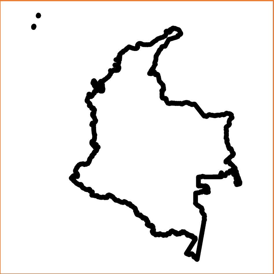
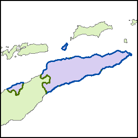
Colombia administrative level 0 (international / shoreline) polygon symbolization.
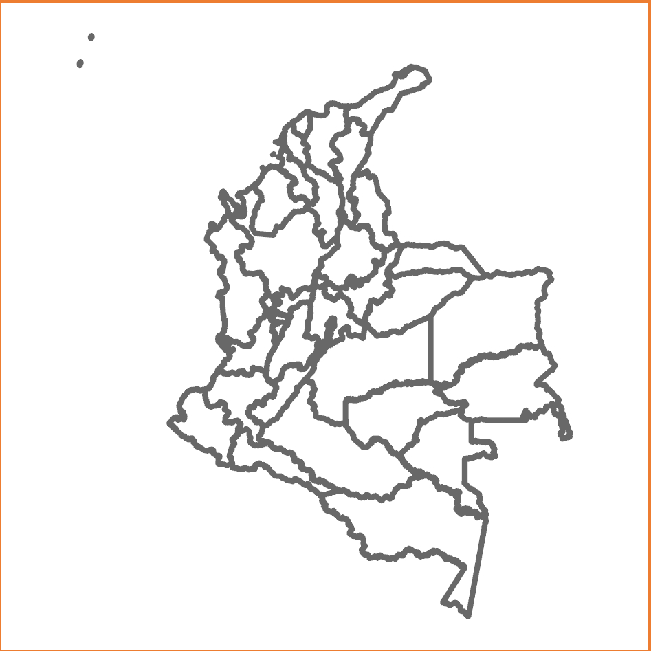
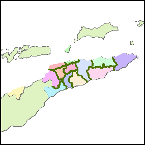
Colombia administrative level 1 (department / capital district) polygon symbolization.
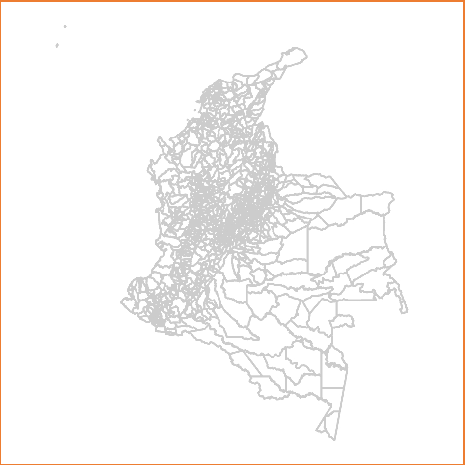
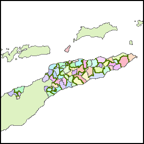
Colombia administrative level 2 (municipality) polygon symbolization.
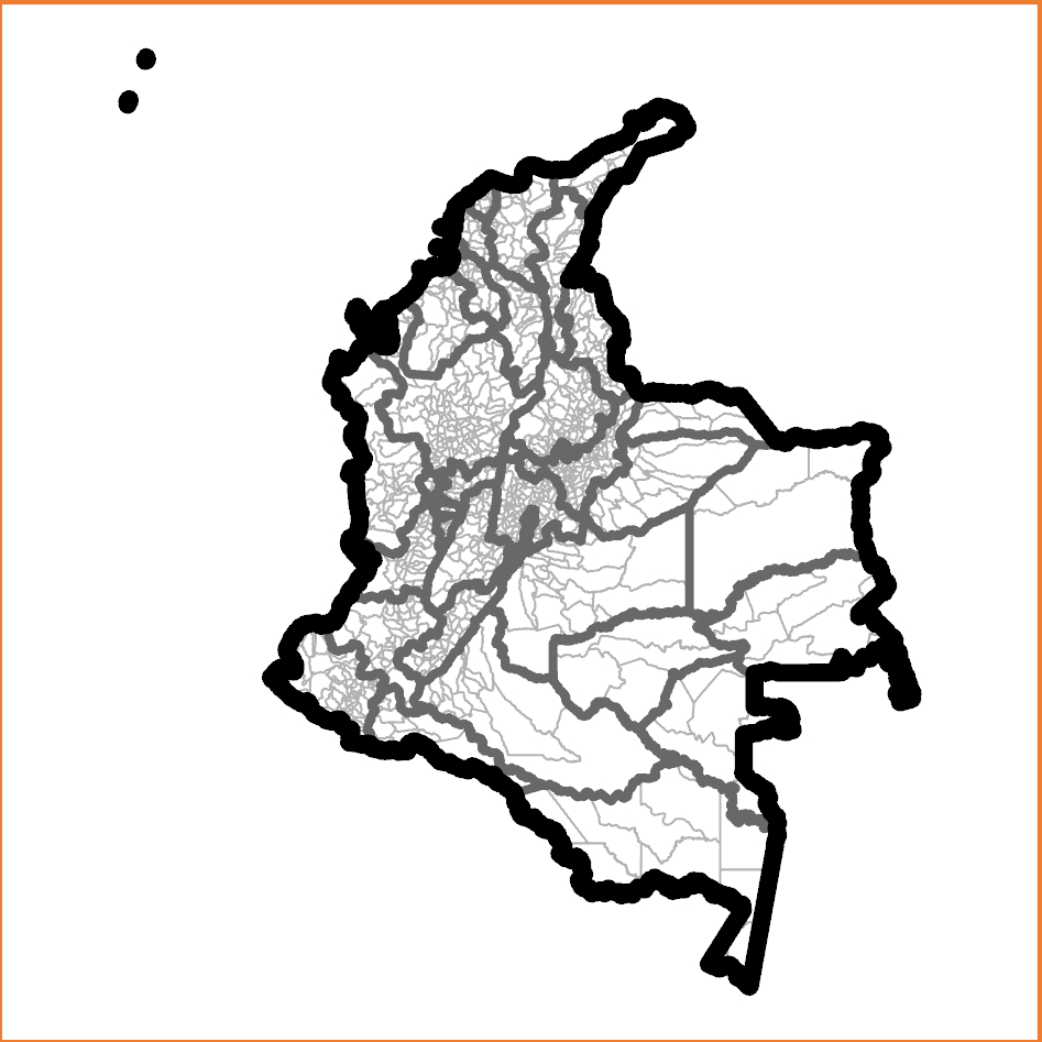
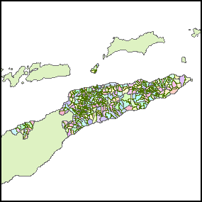
Colombia, crude administrative level 0, 1, and 2 polygon symbolization. The shoreline is not clearly defined.
Preferred lines symbology example
Colombia, administrative level 0, 1, 2, and shoreline lines symbolization
The preferred symbolization applies distinct symbologies to specifically labelled line features. If a line separates polygons with different administrative level 3 features, but the polygons on each side have the same administrative level 2 P-codes, then that line is an administrative level 3 boundary.
For example, if a feature in an Australian lines shapefile separates different counties (administrative level 2 features), but the polygons on each side have the same State (administrative level 1 feature) P-codes, then that line is an administrative level 2 boundary.
No line feature relies on its symbol obscuring other layers, and special features like shorelines or disputed boundaries can be symbolized distinctly at the same level.
Methodology
It may be useful to consider a narrative description of the methodolgy
- The polyline layer is created from the lowest administrative level polygon layer. This layer type contains individual lines between pairs of adjacent polygons and along the outer edges of peripheral polygons.
- An attribute field in the lines table, 'admLevel' is populated with the administrative level of each line feature.
STEP 1: Create the polyline layer.
The goal is to create a lines shapefile with individual line features between nodes and left and right polygon identifiers. (Polygon shapefile exterior features have their left polygon identified as '-1'.) This can be performed with ArcGIS 'Advanced' license or the registered version of ET GeoWizards. This process is not possible with ArcGIS desktop or ArcGIS Pro 'basic' or 'standard' licenses.
The input features will be the polygon shapefile with the lowest available administrative level. This is the only shapefile that can provide all desired arcs.
Run the ArcGIS ‘Polygon to Polyline’ tool (Toolbox > Data Management Tools > Features > Polygon To Line) with: "Input Features" = (lowest administrative level polygon shapefile); "Output Feature Class" = (as desired); "Identify and store polygon neighbouring information" selected; and all environment settings set as default.
(Illustrations are for ArcGIS Pro.)
Sample input parameters:

Sample output (partial):
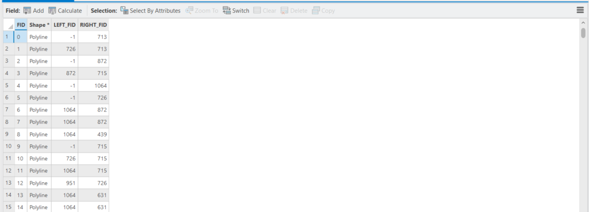
This process generates a lines shapefile with one line ('arc') along each border between nodes, and identifies the left and right polygon Feature Identifiers (FIDs) for each line feature. By convention, the outer polygon boundary is always stored in a clockwise direction so while every line will have a polygon on its right; lines on the exterior of the input shapefile will have no polygon on their left. The attribute table indicates these cases with the LEFT_FID = -1.
The remaining processes are completed in ArcGIS Desktop or Pro, regardless of the software environment used above. (Illustrations are for ArcGIS Pro.)
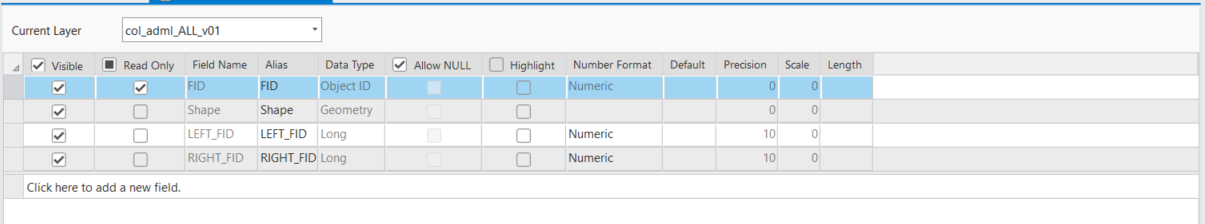
STEP 2: PREPARE THE P-CODE FIELDS IN THE POLYLINE SHAPEFILE
The next goal is to prepare fields to contain the P-codes at each level for the polygons on the left and right side of each arc.
- Add fields to the output boundary polyline shapefile according to the administrative level of the polygon layer used:
| Administrative levels in boundary polygon shapefile | Required new fields in boundary polyline shapefile. (Field names are suggested but not mandatory) |
|---|---|
| ADM0 | 'admLevel' (integer) |
| ADM1 | 'ADM0_L', 'ADM0_R' (normally text); 'admLevel' (integer) |
| ADM2 | 'ADM0_L', 'ADM0_R', 'ADM1_L', 'ADM1_R' (normally text); 'admLevel' (integer) |
| ADM3 | 'ADM0_L', 'ADM0_R', 'ADM1_L', 'ADM1_R', 'ADM2_L', 'ADM2_R' (normally text); 'admLevel' (integer) |
| ADM4 | 'ADM0_L', 'ADM0_R', 'ADM1_L', 'ADM1_R', 'ADM2_L', 'ADM2_R', ADM3_L', ADM3_R (normally text); 'admLevel' (integer) |
We need fields to contain the P-codes for all but the lowest administrative level of the polygon shapefile. For instance, if the boundary polygon shapefile extends to administrative level 3, we need fields to contain the P-codes for administrative levels 0, 1, and 2, for both LEFT and RIGHT. Note that in the unusual case of numeric P-codes, the new fields should also be numeric. The LEFT and RIGHT fields can be removed after STEP 4 is complete, so their names do not have to be those shown.
- Verify that the admLevel values have all been set to zero. Calculate them to zero if they are not.
STEP 3: POPULATE THE POLYLINE P-CODE FIELDS
The goal of this step is to copy the correct LEFT and RIGHT P-codes into the 'ADM1_L' etc. field for every arc. This requires a JOIN between the polygon shapefile and lines shapefile, first using the LEFT FID and then the RIGHT FID. When the LEFT join is established, the left polygon P-codes are copied into the appropriate waiting field (such as 'ADM2_L'). When all LEFT P-codes are copied into the appropriate fields, the JOIN using the LEFT_FID is removed and a new join using the RIGHT FID is established and the RIGHT P-codes are copied.
In Step 4 we will compare the LEFT and RIGHT P-codes at each administrative level to determine the administrative level of each arc.
- Right-click the polyline shapefile used for the lines shapefile creation, then select "Joins & Relates" > "Add join..." and provide the Join Data as follows:
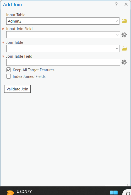
- Input table = lines shapefile
- Input Join Field = LEFT_FID
- Join table = polygons shapefile
- Join table field = FID
Although not essential, it may be useful to click "Validate Join".
Typical validation message:
Start Time: 05 October 2023 14:55:43
Checking for invalid characters...
Checking workspaces...
The join is being done between different workspaces. Performance is lost due to the join being done client side.
Checking for field indexes...
The join field LEFT_FID in the table Lines layers.col_adml_ALL_v01.shp is not indexed. To improve performance, we recommend that an index be created.
Checking for OIDs...
Checking for join cardinality (1:1 or 1:m joins)...
A one - to - one join has matched 4291 records.
The input table has 4493 and the join table has 1122 records.
Succeeded at 05 October 2023 14:56:49 (Elapsed Time: 1 minutes 5 seconds)
Do not expect all records to match - because the ‘left’ side of all exterior lines will have no neighbouring polygon. Do not worry if you receive a “Field names that match reserved words should not be used in database schema and can cause the join to fail. The following fields match reserved words….” message. Close the 'Join Validation' dialogue box after inspecting the result.
’
- Open the output polyline shapefile attribute table
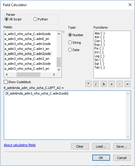
- Use the Field Calculator to calculate all the LEFT_An values (for the LEFT_An files recently added to the polyline shapefile) equal to the corresponding administrative levels of the polygon shapefile. (ArcGIS may require you to begin an edit session.)
| Administrative levels in boundary polygon shapefile | Required calculations |
|---|---|
| Administrative levels 0 and 1 | polyline shapefile 'LEFT_A'0 = polygon shapefile 'ADM0_PCODE' |
| Administrative levels 0, 1, and 2 | polyline shapefile 'LEFT_A0' = polygon shapefile 'ADM0_PCODE' polyline shapefile 'LEFT_A1' = polygon shapefile 'ADM1_PCODE' |
| Administrative levels 0, 1, 2, and 3 | polyline shapefile 'LEFT_A0' = polygon shapefile 'ADM0_PCODE' polyline shapefile 'LEFT_A1' = polygon shapefile 'ADM1_PCODE' polyline shapefile 'LEFT_A2' = polygon shapefile 'ADM2_PCODE' |
| Tip |
|---|
| Usually when the Field Calculator is re-opened during an editing session it maintains the previous calculation expression ("[tl_admbnda_adm3_who_ocha_C.adm2code]" in the above example. Therefore is is usually only necessary to edit the administrative level number to prepare the next calculation. |
- Close the attribute table, remove the join, and establish a new join basing on 'RIGHT_FID'. Anticipate all records matching.
- Open the output polyline shapefile attribute table.
- Use the Field Calculator to calculate all the RIGHT_An values (for the RIGHT_An files recently added to the polyline shapefile ) equal to the corresponding administrative levels of the polygon shapefile.
- Remove the join.
STEP 4: CALCULATE THE ADMINISTRATION LEVELS
ADMINISTRATIVE LEVEL 0
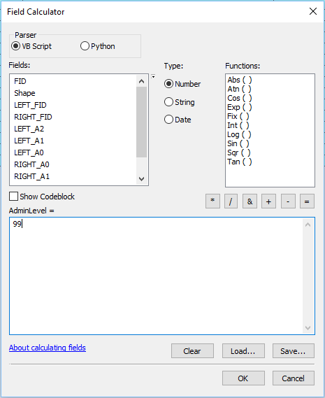
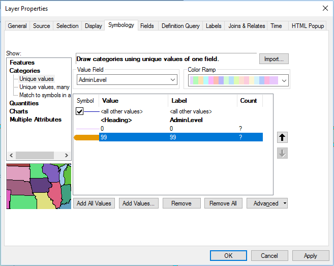
- Verify that admLevel was set to 0 for all features when the field was created. If this is indeed the case then it is only necessary to adjust admLevel to 99 for shoreline features according to the SHORELINE TREATMENT section below. Higher administrative level boundaries will be re-coded later.
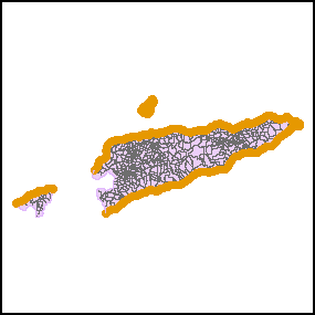
SHORELINE TREATMENT
- At this stage all features will have the default admLevel = 0, indicating international boundaries. If there are shorelines, they must be coded to 99. Jump to the HIGHER ADMINISTRATIVE LEVELS section below if there are no shorelines.
- Open an editing session for the line shapefile.
- If the lines layer is complex it may be useful to use a defininition query (described below) to filter only the 'internatinoal' boundaries. ADD EXPLANATION HERE
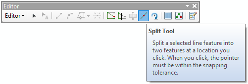
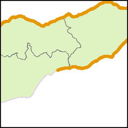
- Manually select line segments that represent shorelines (splitting line segments where an international border meets the water). It may be useful to add a world country layer or neighbouring country layers.
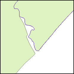
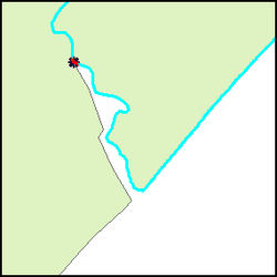
| TIP: Displaying the input polygon shapefile can suggest the location of individual line shapefile segments, which makes them easier to select. |
|---|
|
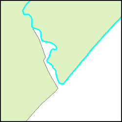
- calculate admLevel = 99.
| TIP: For complex cases, select and calculate the line segments in sections. Establish line symbology that clearly distinguishes the calculated segments. |
|---|
|
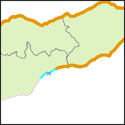
Check carefully for discontinuities
HIGHER ADMINISTRATIVE LEVELS
Administrative level 1
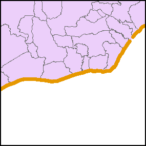
Set a definition query for LEFT_A0 = RIGHT_A0 and LEFT_A1 <> RIGHT_A1.
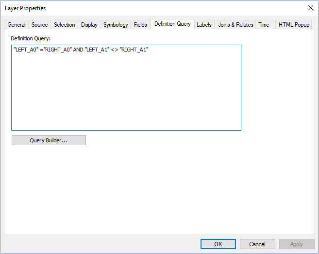
| Explanation: Definition query "LEFT_A0 = RIGHT_A0 and LEFT_A1 <> RIGHT_A1" will select the line features that are not administrative level 0 borders (either shorelines or international borders) but are separating administrative level 1 units. |
|---|
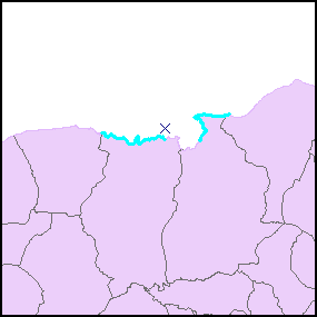
In this map the administrative level 1 polygons are shaded to show that the lines separate administrative level 1 units. |
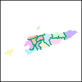
- calculate admLevel = 1.
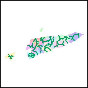
- set a definition query for LEFT_A1 = RIGHT_A1 and LEFT_A2 <> RIGHT_A2;
- calculate admLevel = 2.
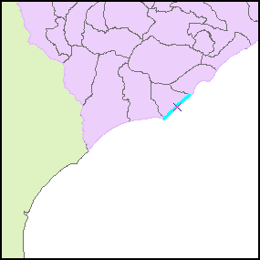
In this map the administrative level 1 polygons are colored to show that the lines are only inside the polygons |
|---|
- Set a definition query for 'LEFT_A'2 = 'RIGHT_A2'; calculate admLevel = 3.
| Explanation |
|---|
International borders and shorelines
Administrative level 1 lines:
Administrative level 2 lines
Administrative level 3 lines |
- Optionally, delete the 'LEFT_x' and 'RIGHT_x' fields.
Some COD-AB (and COD-EM) datasets include politically sensitive line features that may require special symbology. These features are given special admLevel codes in the 10 to 90 range and are specified in the COD HDX descriptions.
Related articles