Table of Contents
Introduction
...
Colombia, crude administrative level 0, 1, and 2 polygon symbolization
Preferred lines symbology example
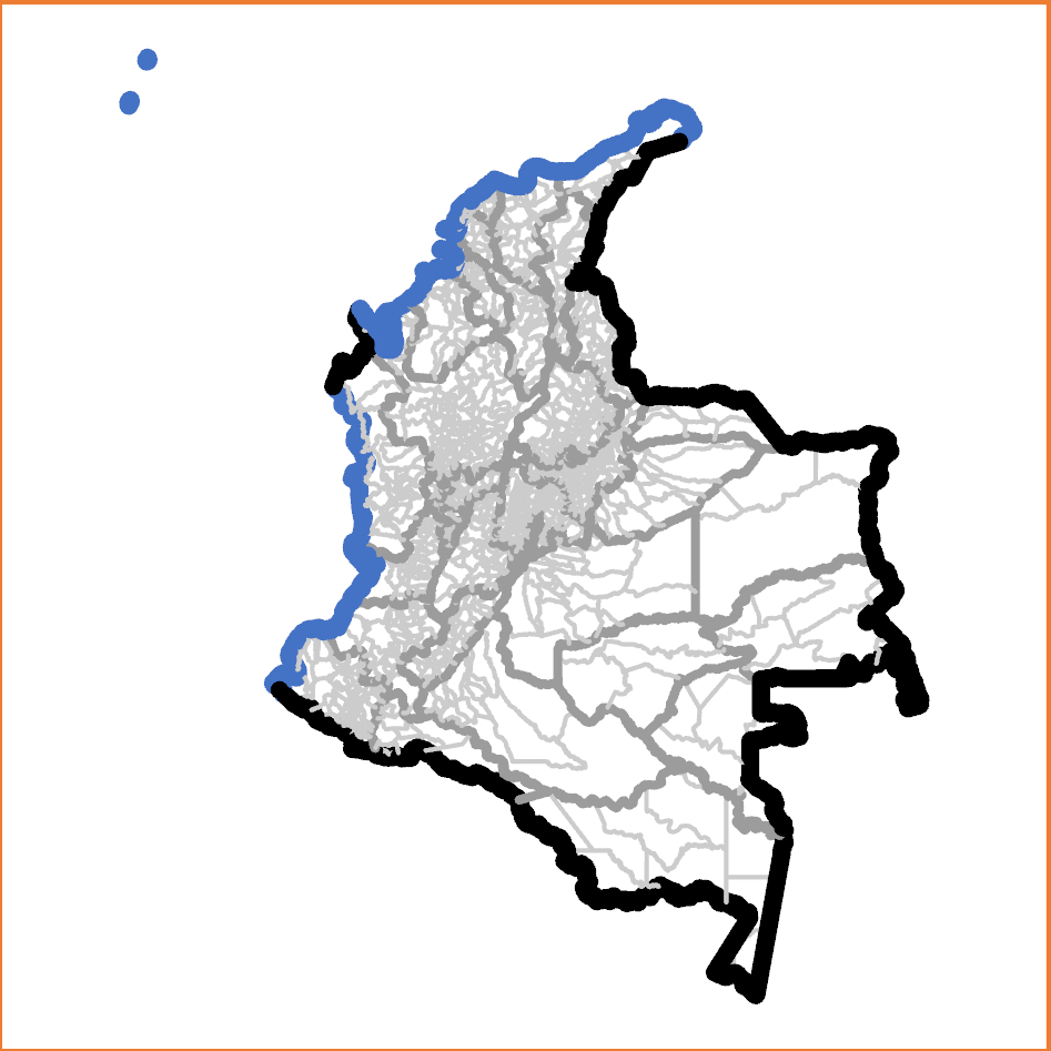
Colombia, administrative level 0, 1, 2, and shoreline lines symbolization
The preferred symbolization applies distinct symbologies to specifically labelled line features. If a line separates polygons with different administrative level 3 features, but the polygons on each side have the same administrative level 2 P-codes, then that line is an administrative level 3 boundary.
For example, if a feature in an Australian lines shapefile separates different counties (administrative level 2 features), but the polygons on each side have the same State (administrative level 1 feature) P-codes, then that line is an administrative level 2 boundary.
No line feature relies on its symbol obscuring other layers, and special features like shorelines or disputed boundaries can be symbolized distinctly at the same level.
Methodology
It may be useful to consider a narrative description of the process in the reverse order of steps.
An attribute field in the lines table, 'admLevel' is populated with the administrative level of each line feature.
STEP 1: Create the polyline shapefile.
The goal is to create a lines shapefile with individual line features between nodes and left and right polygon identifiers. (Polygon shapefile exterior features have their left polygon identified as '-1'.) This can be performed with ArcGIS 'Advanced' license or the registered version of ET GeoWizards. This process is not possible with ArcGIS desktop or Pro 'basic' or 'standard' licenses.
The input features will be the polygon shapefile with the lowest available administrative level. This is the only shapefile that can provide all desired arcs.
| Software environment | Methodology |
|---|---|
| ArcGIS Desktop or Pro ('Advanced' license) | Run the ArcGIS ‘Polygon to Polyline’ tool (Toolbox > Data Management Tools > Features > Polygon To Line) with: "Input Features" = (input lowest administrative level polygon shapefile); "Output Feature Class" = (as desired); "Identify and store polygon neighbouring information" selected; and all environment settings set as default. (Illustrations are for ArcGIS Pro.) Sample input parameters:
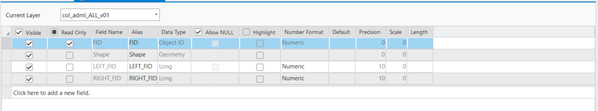
Output attribute fields:
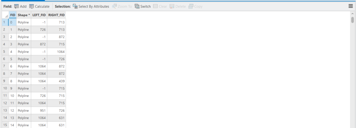
Sample output (partial):
This process generates a lines shapefile with one line ('arc') along each border between nodes, and identifies the left and right polygon Feature Identifiers (FIDs) for each line feature. By convention, the outer polygon boundary is always stored in a clockwise direction so while every line will have a polyon on its right, lines on the exeteror of exterior of the input shapefile will have no polygon on their left. The attribute table indicates these cases with the leftLEFT_FID = -1. The left_FID and right_FID attributes enable the administrative level determination described in Step 4; but this is only after establishment of the left and right polygon administrative levels. THIS ARTICLE WILL BE UPDATED AND COMPLETED SHORTLY. |
| ET GeoWizards registered version | Run the Polygons TO Polylines Advanced tool
Select the 'OBJECTID' field for the 'Link field'. Do not select 'Export points'. With newer versions of ET GeoWizards it may be necessary to make and select a new item, with values equal to 'FID' for this purpose. |


...
The remaining processes are completed in ArcGIS Desktop or Pro, regardless of the software environment used above. (Illustrations are for ArcGIS Pro.)
STEP 2: PREPARE THE P-CODE FIELDS IN THE POLYLINE SHAPEFILE
The next goal is to prepare fields to contain the P-codes at each level for the polygons on the left and right side of each arc.
- Add fields to the output boundary polyline shapefile as follows:
| Administrative levels in boundary polygon shapefile | Required new fields in boundary polyline shapefile |
|---|---|
| Administrative level 0 | 'admLevel' (integer) |
| Administrative levels 0 and 1 | 'LEFTADM0_A0L', 'RIGHTADM0_A0R' (normally text); 'admLevelladmLevel' (integer) |
| Administrative levels 0, 1, and 2 | 'LEFTADM0_A1L', 'LEFTADM0_A0R', 'RIGHTADM1_A0L', 'RIGHTADM1_A1R' (normally text); 'admLevel' (integer) |
| Administrative levels 0, 1, 2, and 3 | 'LEFTADM0_A2L', 'LEFTADM0_A1R', 'LEFTADM1_A0L', 'RIGHTADM1_A0R', 'RIGHTADM2_A1L', 'RIGHTADM2_A2R' (normally text); 'admLevel' (integer) |
Note We need fields to contain the P-codes for all but the lowest administrative level of the polygon shapefile. For instance, if the boundary polygon shapefile extends to administrative level 3, we need fields to contain the P-codes for administrative levels 0, 1, and 2, for both LEFT and RIGHT. Note that in the unusual case of numeric P-codes, the new fields should also be numeric. The LEFT and RIGHT fields can be removed after the process STEP 4 is complete, so their names do not have to be those shown.
- Verify that the admLevel values have all been set to zero. Calculate them to zero if they are not.
...
STEP 3: POPULATE THE POLYLINE P-CODE FIELDS
The goal of this step is to copy the correct LEFT and RIGHT P-codes into the 'ADM1_L' etc. field for every arc. This requires a JOIN between the polygon shapefile and lines shapefile, first using the LEFT FID and then the RIGHT FID. When the LEFT join is established, the left polygon P-codes are copied into the appropriate waiting field (such as 'ADM2_L'). When all LEFT P-codes are copied into the appropriate fields, the JOIN using the RIGHT FID is established and the RIGHT P-codes are copied.
In Step 4 we will compare the LEFT and RIGHT P-codes at each administrative level to determine the administrative level of each arc.
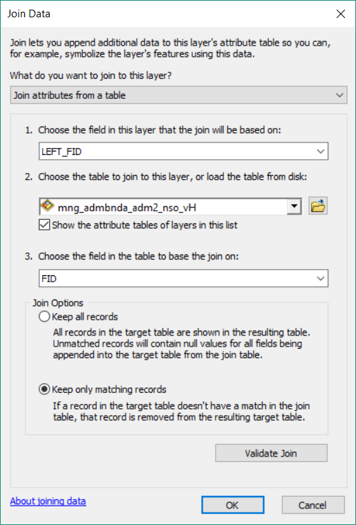
- Right-click the polyline shapefile > shapefile used for the lines shapefile creation, then select "Joins & Relates" > "JoinAdd join..." (or properties > Joins & Relates) and provide the Join Data as follows:
- "What do you want to join to this layer?" = Join attributes from a table
- "Choose the field in this layer that the join will be based on:" = LEFT_FID
- "Choose the table to join to this layer, or load the table from disk:" = (the input polygon shapefile)
- "Choose the field in the table to base the join on:" = OBJECTID (or FID) Select "Keep only matching records". These will be the line features that are not boarding the sea or a neighboring country. If you do not do this, the field calculation stages described below may fail because un-joined records are included in the table.
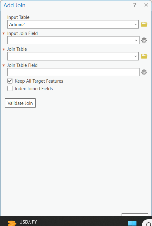
- Input table = lines shapefile
- Input Join Field = LEFT_FID
- Join table = polygons shapefile
- Join table field = FID
Typical validation message:
Start Time: 05 October 2023 14:55:43
Checking for invalid characters...
Checking workspaces...
The join is being done between different workspaces. Performance is lost due to the join being done client side.
Checking for field indexes...
The join field LEFT_FID in the table Lines layers.col_adml_ALL_v01.shp is not indexed. To improve performance, we recommend that an index be created.
Checking for OIDs...
Checking for join cardinality (1:1 or 1:m joins)...
A one - to - one join has matched 4291 records.
The input table has 4493 and the join table has 1122 records.
Succeeded at 05 October 2023 14:56:49 (Elapsed Time: 1 minutes 5 seconds)
- Optionally, click the ‘Validate Join’ button. Do not expect all records to match - because the ‘left’ side of all exterior lines will have no neighboring polygon. Do not worry if you receive a “Field names that match reserved words should not be used in database schema and can cause the join to fail. The following fields match reserved words….” message. Close the 'Join Validation' dialogue box after inspecting the result.
...